Posts

Showing posts from December, 2017

Station Matrix System or Main Video Router System

Image
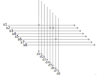
Station matrix or router enhances the professionalism in baseband operational activities. The matrix system is like the digital exchange that performs signal routing. The signal routing may include analog video signal, digital video signal, analog audio signal, digital audio signal etc. Station matrix system deals with route creation in commercial broadcast operation. The route is established between the router destination and source. The main facility is to make certain sources to be available for various destinations what are connected to the station matrix. This feature decreases the number of distribution modules needed for the whole station. The routing system is named as matrix because it performs its operational activity in such a way that follows the mechanism of cross point matrix. The matrix system has some input ports and output ports. The input ports are regarded as source of the matrix and the output port is regarded as the destination port. Video is m

Connector used in TV Channel

Image
n broadcast engineering industry, there have to use various connector and cable for different purpose. Here I will describe some connector with image and usage. Connector # 1 Connector Name: XLR Connector Usage: It is mainly used for audio signal connectivity .  Beside this it is used for stage lighting equipment,  low-voltage power supplies and other applications. It has 3 to 7 pins. Image:  Figure: XLR Connector   Figure: Cable connection of 3 pin XLR Connector. Connector # 2 Connector Name: BNC (Bayonet Neill–Concelman or British Naval Connector or Bayonet Nut Connector) Connector Usage: BNC connector is attached to the ends of coaxial cables. It can be used for connecting RF signals, aerospace electronics and video (analog and digital) signals. It is the alternative to RCA for professional video. Home usage electronics appliance such as televisions and DVD players etc. have BNC connectors as long as RCA connector to deliver c

DSNG system process flow?

Image
DSNG stands for Digital Satellite News Gathering. DSNG system is used as mobile earth station. To perform live broadcasting from a remote place where any physical link like optical fiber, transmission wire,  radio link are not available, then the satellite link is the only way to send the raw footage to the main TV station. The DSNG system is approximately similar to the earth station system together with a mini program control system. The signal flow in the DSNG system as like as below.  Figure: Block diagram of DSNG system workflow TV station can use the same satellite or different satellite for main up-link and DSNG system.   After transmitting the raw footage by DSNG, main station receives that signal. Now it comes to the base band section, processed and then made ready for final on-air through the main up-link. Figure: Up-link and down-link procedure of  DSNG system

Sample Down Link Parameter

To receive a FTA (Free to Air) or CAS (Conditional Access) channel, an earth station engineer needs know to some parameters of that specific channel. Those are called down-link parameter of that channel.  First need the satellite orbital position. Down-link wave polarization may be horizontal or vertical. Those who use cross polarization, if their up-link polarization is vertical then down-link polarization will be horizontal and vice versa. For most the C band channel, they use cross polarization. As video compression technique MPEG-2 and MPEG-4 are generally used. As DVB system DVB-S and DVB-S2 are used. For HD channel MPGE-4 as video compression technique and DVB-S2 as DVB system are used. The main parameter to receive a channel is down-link frequency. It is related with up-link frequency. Another parameter is FEC--Forward Error Correction. It is used as error detection and correction scheme. Generally FEC value is used ¾ or 7/8. Sample: Satellite Name: Apstar 6

Uplink Antenna for Transmitting

Image
The antenna system used by most of the TV stations is double reflected parabolic antenna. It has 3 major parts. -    Horn antenna -    Parabolic Sub reflector -    Parabolic Main reflector Horn Antenna: The waveguide has come to this portion. The certain volume of electromagnetic wave comes here with high energy. For radiation, the horn antenna acts like a radial source (theoretically unidirectional ). Figure: Radiation sequence from the antenna system Parabolic Sub-reflector: The high energetic volume of electromagnetic wave radiated from the horn antenna comes to the sub-reflector and reflected back to the main reflector. Parabolic Main Reflector: The reflected electromagnetic wave from sub reflector comes to the main reflector and according to the law of reflection of the reflected parallel waves, it radiates finally for the travel to satellite.  

What is Sun Outage on Satellite TV

Image
Sun Outage or Sun Transit or Sun Fade Geostationary satellites are fantastic means of communication except for one little problem called sun outage or sun transit or sun fade. It is an interruption in or distortion of geostationary satellite signals caused by interference from solar radiation.  Because the sun is a powerful broadband microwave source and has a noise temperature. The elevated temperature of the sun causes it to transmit a high-level electrical noise signal to the receiving systems. For that reason when the sun passes directly behind the satellite (when viewed from earth) that means the sun is in direct line with a communication satellite,  reception of the relatively weak satellite signals is affected. Due to the many differences in ground station equipment, some stations may experience a complete loss of signal while others may only experience a tolerable degradation of signal.   Figure: Graphical representation of sun outage problem. A most

Azimuth and Elevation Angle for Satellite tracking

Image
Azimuth (Az) The earth station needs to know where the satellite is in the orbit. Then the earth station engineer needs to calculate some angles to track the satellite correctly. These angles are called antenna look angle. The look angles for the ground station antenna are the azimuth and elevation angles required at the antenna so that it points directly at the satellite. With the geostationary orbit the situation is much simpler than any other orbit. As the antenna beam width is very narrow and tracking mechanism is required to compensate for the movement of the satellite about the nominal geostationary position. Three pieces of information that are needed to determine the look angles for the geostationary orbit are a. Earth station latitude b. Earth station longitude c. Satellite orbital position Using these information antenna look angle can be calculated using Napier’s rule (solving spherical triangle). Azimuth angle denotes the horizontal angle measured a

Integrated Receiver Decoder (IRD)

Image
IRD: IRD stand for Integrated Receiver Decoder. This is ultimately a signal receiver. The operational  sequence of IRD is reverse than that of the earth station. The received RF signal by LNB (low noise  blocker) is converted to low band frequency that is operational for IRD.The IRD process this low  band frequency then demodulate it and then decode it according to the encoding system (while  transmitted). And thus the desired base-band signal is recovered. Figure: Down link System of a TV Channel A professional IRD commonly used in satellite TV channel is RX8200 of Ericsson brand.  Figure: Ericsson IRD Rx8200

Symbol rate, Bandwidth and Bit rate Calculation

In satellite communication bandwidth (BW), symbol rate and bit rate are the most vital fact for proper signal transmission. There are many commercial software for BW, Symbol rate and bit rate calculation for TV signal transmission. But the equations of these parameter calculation are as follows. BW= (1+Roll of factor)* Symbol rate In general Roll of factor is 35% Symbol Rate =BW / (1+Roll of factor) and Bit Rate = Symbol rate * Modulation* FEC* (188/204)                                     [when 188 is encoder packet length] or Bit Rate = Symbol rate * Modulation* FEC* (204/188)                                     [when 204 is encoder packet length] Here, FEC = Forward Error Correction. In general FEC is in the range from 1/2 to 7/8. 188/204 = constant Unit ** BW= Hz, KHz, MHz, GHZ ** Symbol Rate= sps or baud, Ksps or Kbaud, Msps or Mbaud, Gsps or Gbaud ** Bit Rate= bps, Kbps, Mbps, Gbps Baud: U nit of signalling speed Baud rate: N umber of symbols transm

Bit Error Rate (BER) and Roll Off Factor

Image
Roll Off  Factor W hen a digital signal is modulated the output would be a waveform with the shape of sin(x)/x. Now this has an infinite bandwidth. So in order to be able to transmit this signal over satellite we need to filter it to reduce the occupied bandwidth. This is done by applying a "raised cosine roll-off filter". This filter is present both at the modulator output stage and at the input of the demodulator (I believe one says these filters are then matched). The steepness and the resulting occupied bandwidth can be set by the parameter roll-off factor. In DVB-S2 it can be 0.20 (20%); 0.25 (25%) or 0.35 (35%) where the  Occupied bandwidth = symbol rate x (1 + roll-off factor). Figure: Occupied bandwidth, Roll off factor and symbol rate 

Sync Pulse Generator - SPG

Image
Master Clock/SPG  C ommercial broadcast systems have many individual sources and destinations, those generate audio  and video signal. In such multi sources/destinations environment every individual device gives outputs in an asynchronous way. This may result jerked or ambiguous frame in raster. After the generation of the video signal it needs a reference (path) to flow. If the signal finds no path the video signal may give information to the TV receiver other than the desired one. In multi sources destination environment it is desired for all signals to be synchronous with each other. For that purpose master clock or SPG (synch pulse generator) is used. It provides reference signal to all of the station equipments. It also generates the time code. For sooth and repayable flow the reference signal (black burst signal, colour burst signal) is provided. With respect to this signal the base-band signal flows to its desired destination without being disturbed. SPG sectio

What is Link Budget ?

What is Link Budget? A link budget is accounting of all of the gains and losses from the transmitter, through the medium (free space, cable, waveguide, fiber, etc.) to the receiver in a telecommunication system. It accounts for the attenuation of the transmitted signal due to propagation, as well as the antenna gains, feed line and miscellaneous losses. Randomly varying channel gains such as fading are taken into account by adding some margin depending on the anticipated severity of its effects. The amount of margin required can be reduced by the use of mitigating techniques such as antenna diversity or frequency hopping. A simple (General) link budget equation looks like this: Received Power (dB) = Transmitted Power (dB) + Gains (dB) − Losses (dB) The link budget is an important value that enables engineers to design systems based on the required sensitivity of a receiver at a particular distance. The free space path loss is the loss in signal strength of a sig

Abbreviation Used in Satellite Communication

AFC --- Automatic Frequency Control AFD --- Active Format Description ALC --- Automatic Loudness/Level Control AM ---- Amplitude Modulation AOV --- Angle of View APID --- Audio Payload Identifier  APSK --- Amplitude and Phase-Shift Keying or Asymmetric Phase-Shift     keying  ASI --- Asynchronous standard interface  or   Asynchronous serial interface ATSC --- Advanced Television System Committee. ATM --- Asynchronous Transfer Mode AVC --- Advanced Video Coding AVP ---  Advanced Video Processor  BISS --- Basic Interoperable Scrambling System BPSK --- Binary Phase Shift Keying  BSS --- Broadcast Satellite Service BW --- Bandwidth C&D --- Contribution & Distribution  CA --- Conditional Access CAM --- Conditional Access Module  CAS  ---Conditional Access System CAT --- Conditional Access Table  CBER --- Convolutional Bit Error Rate / Channel Bit Error Rate CBR --- Constant Bit Rate CCW --- Counter Clock Wise CDP

Antenna Noise Temperature, Directivity, Antenna Gain

Antenna Noise Temperature:   It is the measure of all the external noise collected by a receiving antenna. Measured in Kelvin (K). It varies with antenna diameter, elevation angle and antenna polarisation. The larger the antenna, the lower the noise temperature. Major noise sources are cosmic noise (caused due to sun, moon and starts) and ground noise; caused due to noise energy radiated from the soil.   Antenna Directivity Directivity  is a fundamental antenna parameter. It is a measure of how 'directional' an antenna's radiation pattern is . An antenna that radiates equally in all directions would have effectively zero directionality, and the directivity of this type of antenna would be 1 (or 0 dB). Silly side note: When directivity is specified for an antenna, what is meant is 'peak directivity'. Directivity is technically a function of angle, but the angular variation is described by its radiation pattern.  Antenna Gain The term Ante

What is Modulation AM, FM and PM ?

Image
Modulation In electronics and telecommunications, modulation is the process of varying one or more properties of a periodic waveform, called the carrier signal, with a modulating signal that typically contains information to be transmitted. In telecommunications, modulation is the process of conveying a message signal, for example a digital bit stream or an analog audio signal. Modulation of a sine waveform transforms a base-band message signal into a pass-band signal. A modulator is a device that performs modulation. A demodulator (sometimes detector or demod) is a device that performs demodulation, the inverse of modulation.   A modem (from modulator–demodulator) can perform both operations. Amplitude Modulation (AM) Amplitude modulation (AM) is a modulation technique used in electronic communication, most commonly for transmitting information via a radio carrier wave. In amplitude modulation, the amplitude (signal strength) of the carrier wave

What is Bitrate, CBR, VBR ?

What is the bitrate? In telecommunications and computing , bit rate (sometimes written bitrate) is the number of bits that are conveyed or processed per unit of time. Bit is the unit of information.  Remember that 1 byte consists of 8 bits. Video data rates are given in bits per second. The data rate for a video file is the bitrate. So a data rate specification for video content that runs at 1 megabyte per second would be given as a bitrate of 8 megabits per second (8 mbps). The bitrate for an HD Blu-ray video is typically in the range of 20 mbps, standard-definition DVD is usually 6 mbps, high-quality web video often runs at about 2 mbps, and video for phones is typically given in the kilobits (kbps).   Understanding bitrate in video files It’s important to understand how the bitrate control corresponds to video quality and the file size. At the same bitrate, video in a newer codec such as H.264 will look substantially better than an older codec like H.263. Another co

L Band, C Band, Ku Band and Ka Band for Satellite communication

Due to lower frequencies, L-Band is easiest to implement for marine satellite stabilised systems. There is not much L-Band bandwidth available. The higher you go in frequency, the more bandwidth is available, but the equipment needs to be more sophisticated.  L-Band (1-2 GHz) Being a relatively low frequency, L-band is easier to process, requiring less sophisticated and less expensive RF equipment, and due to a wider beam width, the pointing accuracy of the antenna does not have to be as accurate as the higher bands. L-Band is also used for low earth orbit satellites, military satellites, and terrestrial wireless connections like GSM mobile phones. It is also used as an intermediate frequency for satellite TV where the Ku or Ka band signals are down-converted to L-Band at the antenna LNB, to make it easier to transport from the antenna to the below deck, or indoor equipment.  C-Band (4-8 GHz) Satellite C-band usually transmits around 6 GHz and receives around 4 GHz.

Bandwidth, LNA Noise Temperature, Saturation Flux Density and Polarization.

Bandwidth Bandwidth   is another fundamental antenna parameter. Bandwidth describes the range of  frequencies   over which the antenna can properly radiate or receive energy. Often, the desired bandwidth is one of the determining parameters used to decide upon an antenna. For instance, many antenna types have very narrow bandwidths and cannot be used for wideband operation. Bandwidth is typically quoted in terms of   VSWR  (Voltage Standing Wave Ratio, and sounds very complicated. But it is simply a measure of how much power is reflected from an antenna. ) . For instance, an antenna may be described as operating at 100-400 MHz with a VSWR<1.5. This statement implies that the reflection coefficient is less than 0.2 across the quoted frequency range. Hence, of the power delivered to the antenna, only 4% of the power is reflected back to the transmitter. Alternatively, the return loss S11 =20*log10(0.2)=-13.98 dB. Note that the above does not imply that 96% of t

Followers